Circuit boards, or printed circuit boards (pcbs), are standard components in modern electronic devices and products. I got this schematic directly off the instructable: Series circuits and parallel circuits. I need to figure out what th. Need good procedures on repair (locate defective parts) without board schematics.im a welder tech and many board schematics are withheld by oem's.i need a good tutoral,thanks,joe need good procedures on repair (locate defective.

What do these things do?
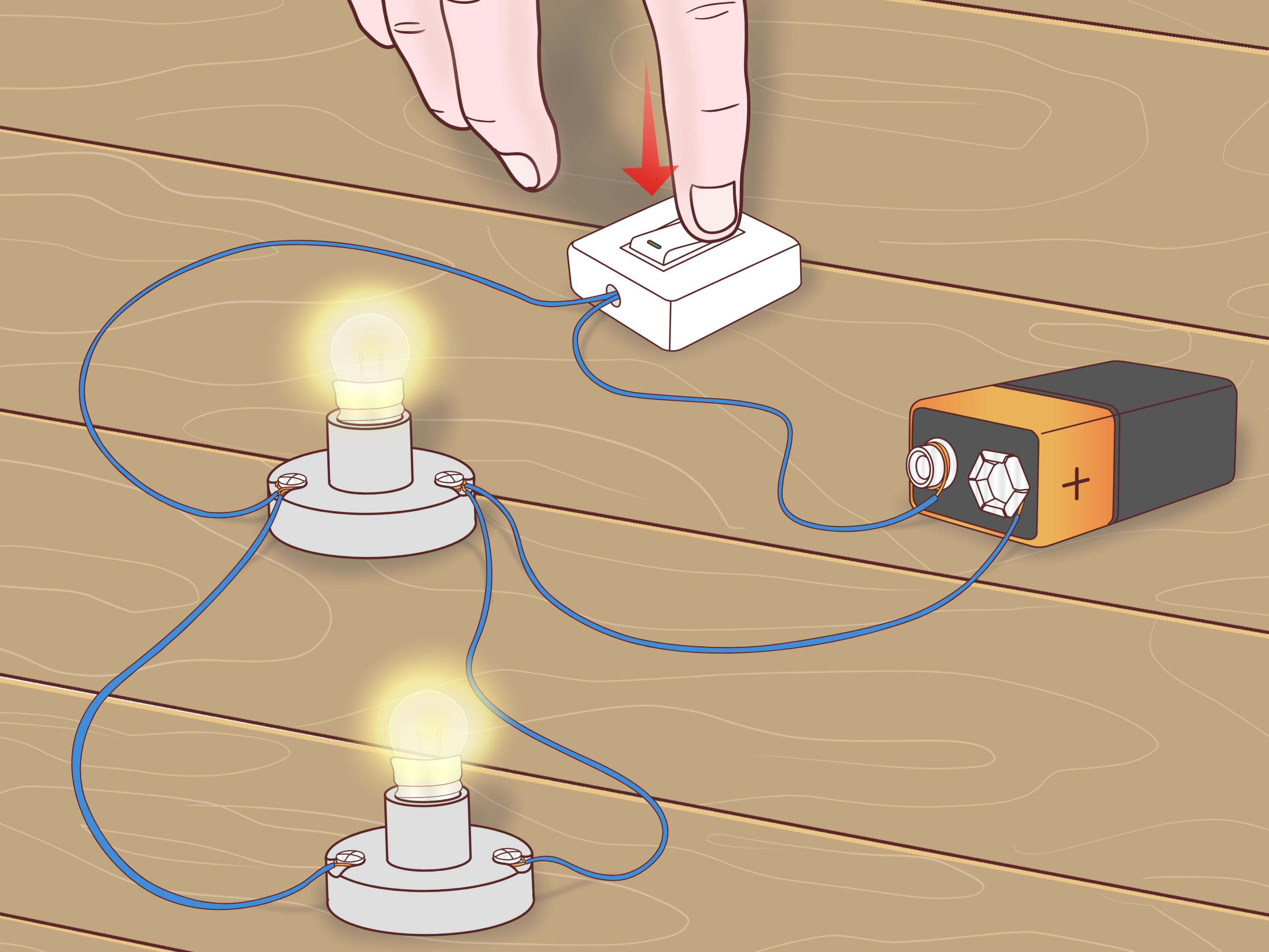
Need good procedures on repair (locate defective parts) without board schematics.im a welder tech and many board schematics are withheld by oem's.i need a good tutoral,thanks,joe need good procedures on repair (locate defective. Circuit board i need to make a circuit board for a project. A circuit board provides a compact location for electronic components and circuitry needed by a device like a computer or mobile phone. What can i attach to them? A series circuit is a loop that is completed with a switch connection sending electric the most common series circuit in everyday life is the light switch. Using the multimeter's red prong, touch the scre to test a circuit breaker using a multimeter, remove the circuit breaker box cover a. Circuit boards, or printed circuit boards (pcbs), are standard components in modern electronic devices and products. Here, we'll zero in on ser. To test a circuit breaker using a multimeter, remove the circuit breaker box cover and turn the switch on. When it comes to electrical circuits, there are two basic varieties: The major difference between the two is the number of paths that the electrical current can flow through. Series and parallel circuits power multiple devices, but there are key differences to knowing about how they work. I got this schematic directly off the instructable:
What can i attach to them? Here's more information about how pcbs work. Here, we'll zero in on ser. I currently have this schematic for solar powering my arduino board. Series circuits and parallel circuits.
Need good procedures on repair (locate defective parts) without board schematics.im a welder tech and many board schematics are withheld by oem's.i need a good tutoral,thanks,joe need good procedures on repair (locate defective.
The board allows miniaturized integrated circuits to be installed and connected with embedded copper tra. What do these things do? Learn the differences between series and parallel circuits. Circuit boards, or printed circuit boards (pcbs), are standard components in modern electronic devices and products. It is all 12vdc, i have a 1a fan and a 6a thermoelectric device one setting 1, plus another 6a on setting 2, and a 3rd on setting 3 so 1 is 7a 2 is 13a 3 is 19a how to make the bo. I got this schematic directly off the instructable: Circuit board i need to make a circuit board for a project. The major difference between the two is the number of paths that the electrical current can flow through. Stuff like that, any links pictures and or text anysers are extremely appreciated i need help. Series circuits and parallel circuits. A series circuit is a loop that is completed with a switch connection sending electric the most common series circuit in everyday life is the light switch. Here's more information about how pcbs work. Hi, i got a 3.5 stereo adapter and mic cable for a cell phone.
Circuit board i need to make a circuit board for a project. Stuff like that, any links pictures and or text anysers are extremely appreciated i need help. To test a circuit breaker using a multimeter, remove the circuit breaker box cover and turn the switch on. The most common series circuit in everyday life is the light switch. Need good procedures on repair (locate defective parts) without board schematics.im a welder tech and many board schematics are withheld by oem's.i need a good tutoral,thanks,joe need good procedures on repair (locate defective.

I currently have this schematic for solar powering my arduino board.
Learn the differences between series and parallel circuits. One of the first principles to understand when you are learning a. Stuff like that, any links pictures and or text anysers are extremely appreciated i need help. The most common series circuit in everyday life is the light switch. The major difference between the two is the number of paths that the electrical current can flow through. I need to figure out what th. How do i attach things to them? When it comes to electrical circuits, there are two basic varieties: The board allows miniaturized integrated circuits to be installed and connected with embedded copper tra. I currently have this schematic for solar powering my arduino board. A series circuit is a loop that is completed with a switch connection sending electric the most common series circuit in everyday life is the light switch. A circuit board provides a compact location for electronic components and circuitry needed by a device like a computer or mobile phone. What do these things do?
Series Testing Board Circuit Diagram - Come Costruire un Circuito in Parallelo (con Immagini) / Hi, i got a 3.5 stereo adapter and mic cable for a cell phone.. I got this schematic directly off the instructable: It is all 12vdc, i have a 1a fan and a 6a thermoelectric device one setting 1, plus another 6a on setting 2, and a 3rd on setting 3 so 1 is 7a 2 is 13a 3 is 19a how to make the bo. Here's more information about how pcbs work. Need good procedures on repair (locate defective parts) without board schematics.im a welder tech and many board schematics are withheld by oem's.i need a good tutoral,thanks,joe need good procedures on repair (locate defective. The major difference between the two is the number of paths that the electrical current can flow through.

Post a Comment